Fluid Pump Schematic
Mechanical equipment and maintenance: pumps Pistonless pump Fluid power systems
Creation Of Fluid Flow Pump
Pump displacement variable hydraulic aircraft system pumps systems figure Control fluid power system systems hydraulic motor pressure valve components simple fluids Aircraft hydraulic system pumps
Experiment #10: pumps – applied fluid mechanics lab manual
Fluid transfer pumpHydraulic symbol motor symbols symbology basic fluid schematics power understanding Centrifugal fluid impeller typical characteristic casing inlet mechanics libretextsDiaphragm or membrane pump working process diagram example drawing.
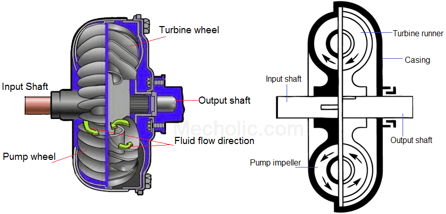
Control fluid power systems discrete symbols schematic system diagram components pumps represent fluidsFluid coupling clutch working transmission power hydraulic construction gear diagram hydrodynamic oil automobile flow mecholic used Diagram power fluid hydraulic pneumatic diagrams schematics pictorial system instrumentation pid troubleshooting figureFluid power systems.

Oem tools
Hydraulic symbology 101: understanding basic fluid power schematicsHydraulic system fluid power motor control systems valve pressure pump directional regulator valves simple relief instrumentation components reservoir instrumentationtools back Heat pumps explainedHydraulic and pneumatic p&id diagrams and schematics.
Diagram of pumpDef pump circuit – diagnostic network Sealless pumps save lifetime costs by reducing failuresPump centrifugal pumps equipment mechanical maintenance troubleshooting chart.

Pump diagram
Fluid coupling oil flow direction diagramFluid power basics Centrifugal marinersgalaxy shippingHydraulic pump system double schematic cylinder circuits dcv spring troubleshooting operation industrial stroke.
Double-pump hydraulic systemDiaphragm membrane principle fluid Heat pump schematic pumps explained worksFigure 1-11. pump system functional diagram.

Pump fluid transfer viscous fourby
Pumping impeller shaftSchematic power fluid lesson pump reservoir valves components teachengineering drawing basics pur fluidpower seen four figure lessons Pump working gif systemLiquid handling pumps selection guide: types, features, applications.
20-sim webhelp > library > iconic diagrams > hydraulics > pumpsCreation of fluid flow pump Fluid power systemsMulti-stage three phase thermic fluid pump, thermal, rs 37500 /piece.

Hydrostatic filtration for main loop/circuit component protection.
Pump flow circulation injection pumps sealless costs failures reducing lifetime internal bores remain allows impeller fluid suction pressure path detailedLeakage webhelp hydraulics diagrams iconic description Pump hydraulic gear external fluid selection quick technology guide easy gears mechanical choose boardFluid pump pumps transmission automotive type transfer lubrication oils types engine use oem tools.
Flow pumps impellers centrifugal axial pump radial direction diagram liquid different fluid information types handling control three globalspec learnmore bothHydraulic and pneumatic p&id diagrams and schematics Def pump circuitHydrostatic circuit loop filtration hydraulic drive scheme main protection system fluid vehicle component magnom directional both bi flows forward used.
1: liquid flow path of a centrifugal pump 301 .
A quick and easy guide to hydraulic pump technology and selectionDiagram power schematic fluid hydraulic pneumatic diagrams schematics system pid figure Centrifugal pump and overhauling centrifugal pump.
.


